Development Kit ( Nucleo/Arduino Shield )

Nucleo/Arduino Shield
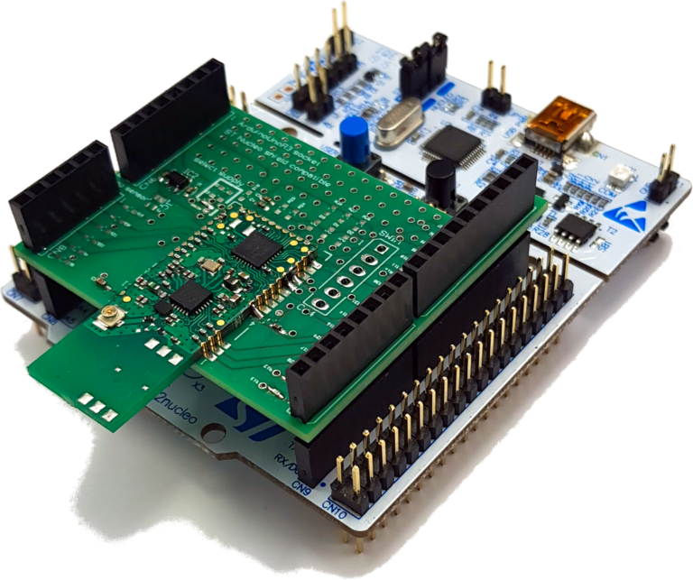
The SIGFOX-DEV1 is a development kit for evaluating the SIGFOX-MOD1 RF-modules. It gives you an easy and fast way to develop IoT applications. Simply write your application on a STM Nucleo or Arduino board, assemble the data into a frame and send it to the SIGFOX-MOD1 by UART. Our module is doing all the work to send your data through the Sigfox network into the cloud. You can monitor the data within the backend of the Sigfox cloud.
We also provide a simple SW example for several toolchains to give a starting point for your own programming.
Features:
– Can be used with SIGFOX-MOD1-C or SIGFOX-MOD1-E ( not included )
– 3 different voltage supply options ( 5V with LDO, 3.3V direct, battery ) selectable by 0Ohm resistors.
– Arduino/Nucleo64 compatible connectors included
– Analog temperature sensor opitional
– Wrap field for own circuitry
– every connector pin is accessable by a jumper to give you flexible routing of the pins to your connector layout.
– 3 LEDs can be mounted
– Pull up resistors can be mounted
– battery holder for CR2540 can be mounted on the bottom side
What is in the bag?
The kit contains the following items:
– 1 baseboard SIGFOX-DEV1 ( without a RF-module )
– 4 connectors
– 1 LDO
– 4 resistor jumpers
– 6 blocking capacitors
SIGFOX-DEV1 on a STM32 Nucleo64
If you want to use the SIGFOX-DEV1 on a STM32 Nucleo you have to take into account, that the UART of the shield is by default connected to the USART2 of the nucleo board, which is by default routed to the VCOM of the STMLink. To connect USART2 of the nucleo board to the shield and disconnect it from STMLink 2 Jumpers on the bottom side of the nucleo board have to be changed. This is also explained in detail in the user manual of the nucleo boards.
But don’t worry it is really easy and here is a before/after photo of what has to be done.
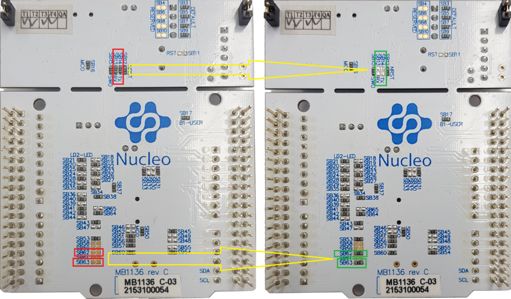
You have to remove resistor jumper SB13 and SB14 and place them onto SB62 and SB63.
This connects the USART2 to the Arduino connector CN9.
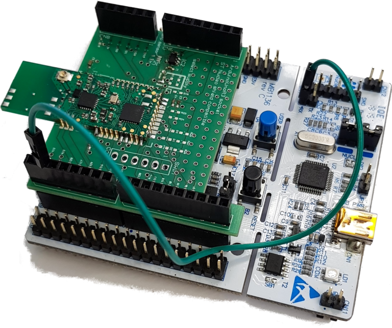
This gives you the possibility to use the STMLink VCom to monitor what your application is sending to the shield by connecting the RX of the STMLink VCOM to the TX of the Arduino connector CN9.
basic usage on ST Nucleo64 boards
Basically the connectors of the shield are standard pinning of the ST Nucleo64 boards. So the only things to be aware of is powering the board either from the Nucleo or from somewhere else.
Regarding programming, you have to keep in mind, that the SIGFOX-MOD1 mounted onto the shield needs to be connected and commanded by serial line ( TTL level ) from your host application running on the baseboard. So check the connection between the serial lines. In the above description, the serial line of the module was connected to USART2 of the nucleo board.
So you have to set up your communication within your application to use USART2.
In the current version of the boards, you have Jumpers to select whether the serial line of the module should be routed to USART2 or USART1 of the nucleo board.
basic usage on Arduino
On Arduino boards, you have to check the wiring on your own to connect the serial line to the UART of the Arduino board. Hence the shield is have a jumper connection on every connector pin, so you can easily wire an individual routing.
Regarding programming, you have to implement the AT commands on the serial line within your host application. As this is simply sending and receiving characters, please check the arduino world for examples.